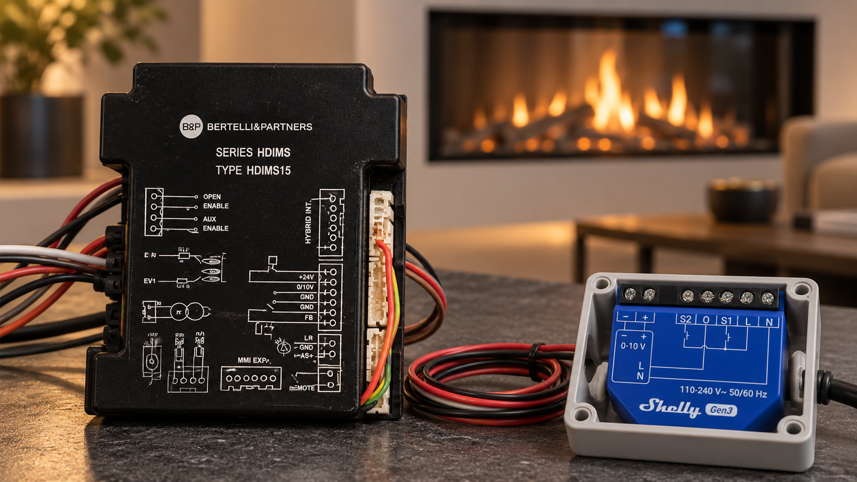
Control a Kalfire gas fireplace through its factory analogue input using Shelly Dimmer 0/1-10V PM Gen3. This integration has been tested on a physical installation with a Bertelli & Partners HDIMS15 controller. Shelly sets the command voltage for starting, changing the flame level and stopping, while the original electronics manage ignition and burner operation. This guide covers the operating principle, hardware, wiring, configuration, local commands, commissioning and troubleshooting.
A gas fireplace already has its own control system. It accepts user requests, carries out the ignition sequence, operates the gas valve assembly and monitors the conditions required for operation. In the installation described here, this role is performed by Bertelli & Partners HDIMS15, used within the Kalfire system.
The Shelly integration uses the existing input for external analogue control. A DC voltage applied to this input has a defined meaning: end the request, request operation or select a modulation level.
The implementation described here has been functionally tested on a physical installation. The Shelly device is Dimmer 0/1-10V PM Gen3, model S3DM-0010WW, and the documented test configuration used firmware 2.0.1. The installation photograph identifies the original controller as SERIES HDIMS, TYPE HDIMS15.
The reference KF2002-00 is retained as an identifier associated with the project. The actual equipment labels, factory cable and appliance-specific wiring diagram provide the basis for technical servicing.
How the control works
Shelly determines the analogue request, while HDIMS15 executes that request through the fireplace’s original operating logic.
The command passes through three stages:
-
The control interface sends an explicit state and level to Shelly.
-
Shelly establishes the corresponding voltage between its + and − terminals.
-
HDIMS15 receives that voltage through the factory input and performs the corresponding function.
The signal conductors carry control information. The fireplace supply, ignition system and gas valve assembly remain in their original electrical arrangement.
After a running request is applied, the controller carries out its normal starting sequence. The visible flame may appear after a delay determined by the appliance state and its operating procedures. A subsequent voltage change adjusts the modulation request.
A received network command, an established voltage and an ignited flame are different events. This distinction matters during commissioning and troubleshooting.
The basic analogue connection does not require a continuously running computer. Shelly maintains its commanded state locally. Shelly Smart Control provides access to the device, while Home Assistant can be added as another control system.
Required equipment
| Item | Role |
|---|---|
| Kalfire gas fireplace with the installed HDIMS15 | Original controller and burner |
| Factory 0/10V input with its associated signal GND | Receives the analogue request |
| Shelly Dimmer 0/1-10V PM Gen3 | Generates the command voltage |
| Appropriate factory interface cable and connector | Provides access to the correct contacts |
| L/N supply for Shelly | Powers the added device |
| Suitable enclosure | Mechanical protection and service access |
| DC voltage meter | Verifies the signal |
| Wi-Fi network | Local and remote access |
The starting point is a fireplace operating normally through its original controls. Before adding external control, establish that the appliance starts, changes its flame level and stops in the usual way.
Mains wiring is carried out by a qualified electrician with the relevant supplies isolated and verified. When reproducing the integration, check the exact interface, permitted potentials and insulation requirements between the circuits being connected. A “0–10 V” label does not, by itself, establish protective electrical separation from the mains.
Understanding the voltage commands
Kalfire documentation describes several functions on one analogue signal. The modulation region occupies part of the overall electrical range. [1, 2]
| Voltage at the input | Documented function |
|---|---|
| 0 V | Flame off |
| Above approximately 1.5 V | Hybrid function on an appliance equipped for it |
| Above approximately 3 V | Heat demand and starting |
| Approximately 3–9 V | Modulation from low to high flame |
| Approximately 9.5 V | ECO mode on a compatible appliance |
The implemented basic control uses zero voltage for stop and running requests above the starting threshold up to 9 V.
Hybrid and ECO are included to explain the input map. They have separate meanings and are kept outside the ordinary flame-modulation scale.
For every accepted request, the voltage reaching the fireplace and the response verified during commissioning should be clear. This makes the commands repeatable.
Percentage, voltage and flame level
In Shelly software, the analogue channel uses the property brightness. In this application, its practical meaning is a command percentage from which the output voltage is produced.
With 0–10 V mode, a linear characteristic and an unchanged 0–100% range mapping, the nominal relationship is:
\[ U=\frac{P}{10} \]
where:
-
U is the voltage in volts;
-
P is the command percentage.
The inverse relationship is:
\[ P=10U \]
| Shelly command | Nominal voltage | Application |
|---|---|---|
| Output Off | Approximately 0 V | Stop |
| On, 30% | Approximately 3 V | Threshold measurement point |
| On, 40% | Approximately 4 V | Low running request |
| On, 60% | Approximately 6 V | Intermediate running request |
| On, 90% | Approximately 9 V | High running request |
| On, 95% | Approximately 9.5 V | Separate ECO command, where applicable |
The table gives nominal requests for the selected scale. Actual meter readings are recorded for the particular device.
60% in Shelly does not automatically mean 60% heating output or 60% gas consumption. It identifies a command to the analogue channel. The resulting flame depends on the fireplace’s characteristics and its controller.
Selecting the low running request
In practice, the low request benefits from some margin above the starting threshold. A value around 4 V provides that margin with the nominal scale used here.
This is the engineering reason for the selected value. It is not a separate factory mode and does not, by itself, establish the burner’s absolute minimum output.
During commissioning, check the low request from a stopped fireplace when it is intended to act as a starting command. Testing it only after combustion has already been established does not cover the same behaviour.
Why this particular Shelly model is used
The Shelly Knowledge Base describes Shelly Dimmer 0/1-10V PM Gen3 as a current sourcing controller. This is the characteristic used in the implemented arrangement to apply a command voltage to the fireplace input. Its documented maximum control current is 35 mA. [3]
The older Shelly Plus 0-10V Dimmer is described as current sinking. Its electrical interaction with a receiver is different, so the similar name is insufficient grounds for substituting it in the tested integration. [4]
| Parameter | Configuration used |
|---|---|
| Device | Shelly Dimmer 0/1-10V PM Gen3 |
| Model | S3DM-0010WW |
| Firmware recorded for the test | 2.0.1 |
| Analogue mode | 0–10 V |
| Supply | 110–240 V AC through L/N |
| Command pair | + and − |
| Output O | Does not supply the fireplace |
The command path in this installation is analogue. It does not use Modbus, an RS485 add-on or a serial converter.
Connecting to HDIMS15
The actual installation photograph shows the markings on the original controller, including 0/10V. The connection follows the functions of this input and its associated reference.
| Shelly side | Fireplace side | Function |
|---|---|---|
| + | Documented 0/10V input | Positive analogue signal |
| − | Signal GND of the same interface | Command reference |
| L | Live conductor of the Shelly supply circuit | Power |
| N | Neutral conductor of the Shelly supply circuit | Power |
| O | Left unconnected | Outside the analogue connection |
Connect the negative signal conductor to the reference associated with the input being controlled. Do not arbitrarily connect it to N, PE or another ground elsewhere in the installation.
Other contacts on HDIMS15 are not interchangeable connection points. Labels such as +24V, PF and FB must not be treated as alternative analogue-input terminals.
Factory cables from different Kalfire generations may have different colours and additional conductors. Identify each function using the correct diagram and by tracing the connection.
If another active external regulator previously operated the same input, disconnect its output before Shelly takes over that role. Two independent voltage sources must not be connected in parallel to the same input.
The fireplace supply remains independent
Relay output O is outside the command path. The original fireplace electronics remain powered through their normal arrangement.
The Off command ends the analogue request. It does not electrically isolate the fireplace for servicing.
This distinction also matters during troubleshooting. If the original controller’s supply has incorrectly been routed through O, switching off the Shelly channel may remove power from HDIMS15. That is a different action from applying a zero-voltage analogue request.
Device placement
Install Shelly in a suitable enclosure outside the heated fireplace area. Assess the actual temperature around it during sustained operation with the enclosure closed.
The documented maximum ambient temperature for this model is 40°C. The original controller’s temperature rating must not be assumed to apply to the added device. [3]
Protect signal wiring against heat, sharp edges and strain. Label the conductors and keep connections accessible for servicing.
The generated cover image is an editorial illustration based on the actual equipment. Technical wiring follows the original markings, installation photograph and electrical documentation.
Baseline settings
Prepare the configuration with the analogue output disconnected from the fireplace.
| Setting | Accepted baseline |
|---|---|
| Operational Mode | 0–10 V |
| Minimum range mapping limit | 0% |
| Maximum range mapping limit | 100% |
| Transition Duration | 0 s |
| Action on power on | Off |
| Auto on | Disabled |
| Night mode | Disabled |
| Other functions changing the output | Disabled during initial verification |
| Running command | Explicit On with a defined level |
| Stop command | Explicit Off |
The operating mode, power-on action and transition settings are described in the Shelly Smart Control guide. [5]
Retaining the 0–100% range keeps the relationship between command percentage and voltage understandable. Changing either mapping limit changes that relationship.
After such a change, the existing 40%, 60% and 90% requests must be reassessed. Where a gamma setting is available for the channel, include it in the transfer check. A linear voltage request uses a linear characteristic.
Zero software transition
At this interface, a gradual transition means deliberately passing through a sequence of command voltages. Some of those voltages have different meanings in the Kalfire input map.
The baseline implementation therefore uses Transition Duration = 0 s. The same rule applies to an external client that can specify its own transition.
A zero software transition removes the deliberate fade in the request. The analogue output and fireplace retain their own dynamics, and HDIMS15 continues to execute its normal operating timings.
Correct stopping behaviour
Use explicit output state Off to stop.
The flame may be extinguished while a positive analogue request is still present at the input. Checking shutdown therefore includes both the fireplace response and the physical signal state.
Stored brightness and an active output are also different things. Shelly can retain the previous percentage while the channel is switched off. Displaying that percentage does not prove that the corresponding voltage is still being applied.
Local commands through RPC
The controlled component is light:0. The following requests use the nominal scale described in this guide and directly set the analogue channel’s state. The methods are documented in the Shelly Light API. [6]
Read the configuration:
{"id":1,"method":"Light.GetConfig","params":{"id":0}} Request a nominal 4 V running level:
{"id":2,"method":"Light.Set","params":{"id":0,"on":true,"brightness":40,"transition_duration":0}} Change to nominally 6 V:
{"id":3,"method":"Light.Set","params":{"id":0,"on":true,"brightness":60,"transition_duration":0}} Request a nominal 9 V high running level:
{"id":4,"method":"Light.Set","params":{"id":0,"on":true,"brightness":90,"transition_duration":0}} Stop:
{"id":5,"method":"Light.Set","params":{"id":0,"on":false,"transition_duration":0}} Read the channel status:
{"id":6,"method":"Light.GetStatus","params":{"id":0}} When starting, specify both on: true and the required level. This avoids depending on an unknown stored brightness.
When stopping, send on: false. The physical output behaviour forms part of the verified configuration.
The Light.GetStatus response describes the Shelly channel. It is not independent confirmation of burner ignition or a voltage measurement at the HDIMS15 input.
Commissioning the installation
The following procedure allows the working integration to be reproduced and documented consistently.
-
Identify the equipment. Record the fireplace, HDIMS15, factory cable, Shelly model and firmware.
-
Check the original controls. Establish normal fireplace behaviour before adding the external integration.
-
Prepare Shelly with the signal disconnected. Apply 0–10 V mode, the full range, zero transition and Off after power restoration.
-
Measure the command points. Check the voltage between + and − at Off and at the selected running requests.
-
Check power restoration. With the fireplace disconnected, start from a running request, remove and restore Shelly power, and confirm its actual initial output state.
-
Connect the signal pair. Change conductors only with the relevant supplies isolated and verified.
-
Confirm the initial stop state. Check that no running analogue request is present at the HDIMS15 input.
-
Apply one running request. Allow the normal fireplace sequence to complete and observe ignition.
-
Check modulation. Change levels individually after operation has settled, and verify voltage at the receiving end.
-
Check Off and handset handover. Confirm shutdown and return to the original controls.
-
Check network interruptions. Establish behaviour separately for internet loss, Wi-Fi loss and command-client reconnection.
-
Record the results. Retain the actual measurements and accepted settings.
Measuring first at Shelly and then at HDIMS15 distinguishes a source problem from a cable problem.
If the correct voltage is present at the output but does not reach the input, investigate the connections. If the signal reaches the correct input, the next check concerns the fireplace’s state.
Returning to the original handset
Kalfire documents a restriction on simultaneous use of the analogue input and handset. Release the external request according to the manufacturer’s procedure, after which the original controls can operate the fireplace again. [1, 2]
Test this as a separate function. Successful flame shutdown and successful handset handover are two observations to record individually.
Keep the handset available near the installation. If an error or lockout occurs, check the code and follow the original recovery procedure. Repeatedly sending a start request does not resolve the cause of a lockout.
Behaviour when communication is lost
The physical command path is between Shelly and HDIMS15. The internet connection provides remote access through the cloud service.
Closing the app or disconnecting the phone does not send a stop command. The analogue output may remain at its last accepted request.
When the network returns, check the behaviour of the command clients as well. Some systems may replay a stored request and change the state after reconnection.
The official Shelly integration for Home Assistant provides local communication with the device. When adding it, retain the same accepted limits, explicit commands and zero transition. [7]
What can be reported
| Information | What it establishes |
|---|---|
| Issued command | The command client’s request |
| Shelly state | The state of its channel |
| Measured HDIMS15 input voltage | The physical analogue signal |
| Observed flame | The burner response |
| Information from the original controls | Data provided by the fireplace |
The analogue input is a command path. Reporting burner operation, temperature, faults or gas consumption as measured values requires the appropriate documented feedback sources.
In this implementation, O does not supply the fireplace. Consequently, electrical measurements from the load channel are not used as heating output or gas consumption.
Troubleshooting
| Observation | What to check |
|---|---|
| Shelly accepts the command but the fireplace does not start | Input voltage, correct GND, starting threshold and HDIMS15 state |
| The low request works after ignition but does not start from stopped | Accepted low level and actual voltage relative to the threshold |
| A percentage produces an unexpected voltage | Operating mode, range mapping and gamma where applicable |
| The flame or operating mode changes unexpectedly | A transition, a request outside the modulation region or another client |
| The flame is off but the handset cannot take control | Residual request and the interface-release procedure |
| An old level returns after restart | Power-on state, Auto on and restored external commands |
| A relay clicks without the expected response | Actual analogue voltage and correct separation of O from the fireplace supply |
| The fireplace reports an error | The original code and Kalfire procedure |
| Shelly becomes hot or restarts | Supply, temperature and enclosure placement |
For an unexpected change, record the time, command source, Shelly state and measured signal. This helps distinguish another client’s command from an electrical problem.
Documentation and servicing
The technical record of the tested integration contains:
-
A photograph and identification of HDIMS15.
-
The selected input and associated GND markings.
-
Factory cable details.
-
Shelly model and firmware.
-
A functional wiring diagram.
-
Accepted settings and actual measurements.
-
Results for starting, modulation, stop and power restoration.
-
Confirmed return to the original handset.
After changing firmware, replacing equipment or changing range mapping, repeat the affected checks.
The practical result is working network access to the fireplace’s factory analogue interface. Shelly establishes the voltage, while HDIMS15 executes the request through the original Kalfire logic. The accepted scale, explicit stop and recorded measurements provide a clear basis for subsequent operation and servicing.
Technical references
-
Kalfire Fairo ECO-prestige installation manual, August 2014, section 29.4, printed page 19.